General Information

Triumph Nuts & Bolts

If you’ve ever looked at a parts listing for your Triumph you’ll see that nuts and bolts have cryptic part numbers like KT504 or YN2912. Whilst these look seemingly random, Triumph used a system of part numbers which defines the specification of a particular nut, bolt and washer. Hence armed with a parts book you can work out what the bolt is in plain english.

Nuts

Prefix gives type of nut.

* HN refers to a plain nut.

* YN refers to a nyloc nut.

* JN refers to a jam nut (ie half thickness).

* TN refers to a thin type nyloc.

Last 2 digits give size & thread

* 03 = No. 6 UNF

* 04 = No. 8 UNF

* 05 = No. 10 UNF

* 07 = 1/4 UNF

* 08 = 5/16 UNF

* 09 = 3/8 UNF

* 10 = 7/16 UNF

* 11 = 1/2 UNF

* 12 = 9/16 UNF

* 13 = 5/8 UNF

* 53 = No. 6 UNC

* 57 = 1/4 UNC

Thus a YN2912 is a 9/16″ UNF nyloc

Bolts

Prefix gives type of bolt

* HU refers to a setscrew (threaded all the way)

* HB refers to a bolt.

* KT refers to a countersunk slotted.

* KX refers to a countersunk crosshead.

* PT refers to a pan head slotted.

* PX refers to a pan head crosshead.

First digit (s) defines thread size as per nuts above, but the thread type is always UNF unless the second digit from the right is 5 in which case the thread will be UNC. The last two digits give the length in eighths of an inch (up to 49). Thus a KT504 is a No. 10 UNF, a countersunk slotted head 1/2″ screw.

Washers

Washers prefix gives type

* WP refers to a plain washer.

* WL refers to a lock washer.

* WN refers to a shakeproof washer.

The last two digits give the size as per the chart above for the nuts (03 to 13).

Summary

That’s it, as you can see it’s not too difficult to work out and now you’ll be able to find the right nuts, bolts and washers for your Triumph!

DIY Wheel Alignment

Do-It-Yourself Alignment by Calvin Sanders

Grateful thanks to Calvin Sanders and “The Vintage Triumph Register” ( http://www.vtr.org) for the following article.

I received a lot of interest from fellow British Car owners when I mentioned doing my own alignments with homemade tools, so I took a couple of days and put together this explanation of how I do it, and what tools I use.

When I first said it took $20 in tools I made a quick guess off the top of my head, but here is what you need and a guess of the cost.

  • 15′ of clear vinyl tubing about 5/16″ diameter $3.00 2 12″ rulers – swipe from office supply at work 🙂
  • $0.00 10-20 pieces of fairly stiff floor tiles 12X12″ left over from the last time you replaced kitchen floor $2.00
  • 16″ bubble level from Roses on sale $3.00 Piece of wood long enough to span one wheel from lip to lip $0.00
  • 6″ machinists ruler with 1/32″ or better markings $4.00
  • Carpenters Plumbob on sale at Sears $2.00
  • Some kind of fixture for measuring Caster $????
  • Fishing line – about 40 feet $1.00
  • 4 jack stands – should already have $0.00
  • Magnetic base carpenters Protractor $4.00

Some other ones may help. A Lucas or similar digital protractor is a great tool. If I were to spend much money on any one tool it would be one of these. I think they are about $90, but if anything is worth the money they are. They will just make the job much easier.

OK first make sure your tires all have proper air pressure in them. First you will need to find a level spot. For this I use clear tape and attach the two rulers to the ends of the clear vinyl tubing. then you fill the tubing with water. I usually use the tubing like a straw and draw the water up into the tubing. You need two people to use this as a water level. The idea is the water will be level at both ends of the tubing when the tubing is held upright. You can then stand one ruler where one wheel will be and the other ruler where another tire will be and if the water is at the same level on the two rulers then those two spots are level. You can then adjust the “pads” where the tires will be by making stacks of tile. Each tile is usually about 1/8″ thick so it takes a few tiles to bring up all the low spots up to the highest spot. In your garage you may want to mark these spots and take notes of how many tiles each place needs.

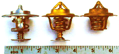
Next you need to find out how true your rims are. I jack up each wheel and sit the jack stand next to the wheel and sit the machinist’s ruler on the jack stand with it extending just to the rim. Then rotate the wheel one turn and see how much run out you have. On most alloy wheels they will have less than 1/32″ which is just fine. On factory steel wheels some wheels may have as much as 1/4″ which will ruin your measurements. Find 2 places on your wheel that are 180 degrees apart and have the same run out measurement. On almost all wheels there is 2 places you can use to measure on, though you may have to search for the spot. I then mark the spots with a pencil or magic marker.

Alternatively you can either check the tire for trueness and use the tire for measuring, or you can make chalk marks around the tire on the edge of the tread and use a nail or something sharp to make a scribe line around the tread surface near the outside and make all measurements to the scribe line. To do this jack the wheel up so it can spin freely and drive a nail through a piece of wood. Lay the piece of wood on the floor so that the point of the nail just touches the tire tread. When the tire is spun around you will have a true line scratched around the tire. I have found this method of measuring to not be as convenient as using the rim, so use the rim if it is possible. If your rims are true you can assume them to always be true unless you run over a curb or something. This means you don’t have to check them every time you align your car.

Next I like to find the centerline of my car. I do this by using the plum bob draped over my inner suspension mounting points and measuring half way between them and finding the center-line. This of course does not work on all cars. Some cars don’t have suspensions that are mirrors of each other, but most do. I will drop the plum bob to the floor and make pencil marks on the floor. Then I will measure on the floor. I found a friends Corvette to have a perfectly straight frame, but to body of the car to be about 1/2″ crooked on the frame. You can’t go by the center of the bumper or anything like this. Once you have found the C/L carry the mark up to the chassis or body. I made a fine white line on the front of the frame and the rear of the body under the bumper on my Mustang GT with a paint marker. Now I measure from the centerline for all measurements.

Now put the car on the leveled pads. It is best to have rolled the car back and forth a few times to get the suspension settled. Also I should mention that I have made pads out of one square foot cuts of 2″X12″ boards with small angled ramps on the fronts of them. This lifts the car up 2″ making suspension parts easier to get to. I then level with the tiles on top of these pads. It works fairly well making the suspension parts easier to reach.

First I like to check the castor. I seldom make any changes to this adjustment. It is also not that critical to have exactly to some spec, but it is important to have each side even. For this I use the Magnetic base protractor. It is accurate to .5 degrees which I think is adequate for castor measurement. On a Strut car I simply place it on the strut and measure the angle of the strut. This may be off slightly from the spec books, bit the error is correct from side to side and it is fairly close. If you have a car with upper ball joints first check your spindles for a machined flat spot that is parallel with the ball joint axis. If this exists then you can simply place the protractor on this surface and measure castor. Many cars have this machined surface for various reasons. If it doesn’t then all is not lost. You will need to make some sort of fixture that will “reach in” to the ball joints. You will need a vertical flat surface with two “arms” extending to the ball joints. A 2X4 with 2 long bolts through it may work. You want a vertical surface parallel with the ball joint axis. You can measure this with the surface with the protractor again. You can also measure this in a similar method to how I will measure camber later for more accuracy. This is of course only necessary if your car has some way to adjust castor, which many do not.

Next I like to measure camber. This is the most important measurement in auto cross in most people’s opinion. I use the short level attached to a piece of wood and the machinists ruler for this. I cut the piece of wood so that it will span across from the top wheel lip to the bottom one. I then attach the level to the piece of wood. I use the wood for a couple of reasons. First I can shim between the wood and the level to correct for errors that may occur in the cheap level. I have found most of them to have some small inaccuracies in them. Also you may need to notch the wood to clear the wheel in the center for the hub or something. I also have different lengths of wood for the different wheel diameters I work with. To correct for errors I use the plumbob. It will hang vertical. I then shim between the wood and the level until it is indicating level when the board is completely vertical.

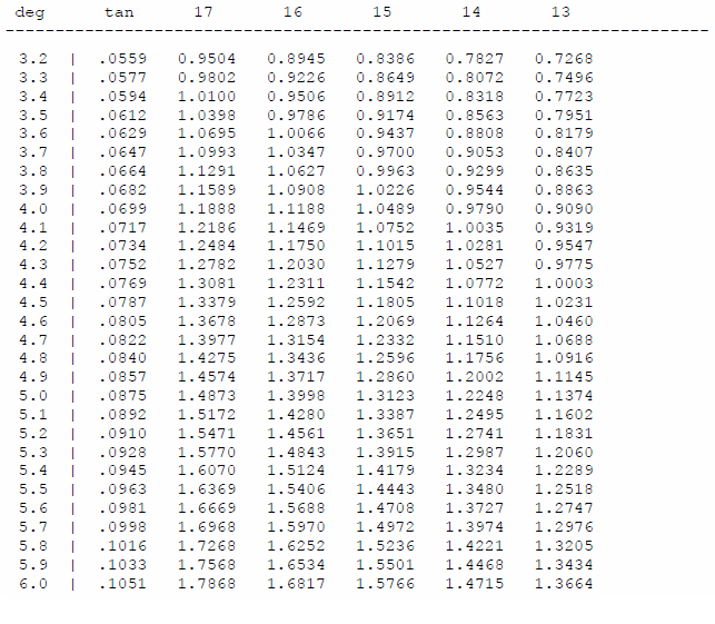
Now you must have the two places on your wheel you found to be true to each other, vertical (straight up and down). If your entire wheel is true then it is a great benefit at this point. Take the piece of wood and the level and span across your rim with the level vertical. Now use the bubble and pull out from the top of the wheel until you are holding the level vertical. Now measure from the piece of wood to the top of your rim. It will be a distance of about 1/4″ or so (assuming you have negative camber. Take this measurement with the machinists ruler. Be as accurate as you can. Then you need to take that distance and divide it by the span distance of the piece of wood. For a 15″ wheel you can just use 15″ and a 16″ wheel 16″ etc. Then look up this number in your old Trig table in your high school trig book. You will need to find the arc tangent of the number you have. The degrees of this will be the camber angle. I have a 10 line basic program that will print a chart for converting these angles I have included in the end of this. I have also included a chart that will convert this measurement without dividing and looking up the measurement. I now prefer to keep my measurements in inches of gap at the top of the wheel rather than converting them to degrees. I keep my log books in this measurement rather than degrees for each car. It only causes a problem if I change the rim diameters of any one car I am working with. For toe in measurement I need to reference the centerline of the car.

First you need to get the measuring points on your wheels at 9 and 3 o’clock. This is where it is helpful to have true wheels, then you don’t have to move the car. You will need the jack stands and fishing line for this, plus the machinists ruler. you want to set up the fishing line outside the sides of the car an equal distance from the centerline of the car. I tie the fishing line to the jackstands so that the line when stretched will be about equal height to the center of the wheel hubs. This does not have to be exact, but close to the wheel hub center. measure out from the centerline to about 3″ outside the wheels. The setup will look like this when viewed from above:

alignment diagram

It’s important to get the fishing line parallel to the centerline of the car. You can’t measure to the rocker panel or the wheel hubs or anything initially because they may or may not be parallel to the centerline. So the first time measure from the centerline that you found before. Now it is good to then measure from the bottom corners of the door or the rocker panel or something and record the measurement in your log book. It will make the setup much faster of you want to change your toe quickly at an event. It should be noted that a perfectly level pad is not necessary for toe setting. It is good to get the car on a fairly level spot but exactly level is not important.

Then to measure the toe measure at the front edge of the rim and the rear edge of the rim and subtract the difference. That will give you the toe measurement. Obviously for toe in the measurement at the rear of the wheel (from the fishing line to the edge of the rim) will be less than the measurement at the front of the wheel. The reverse is true for toe out and the two measurements will be equal for zero toe. The measurements you will be working with will actually be less than what is usually referenced in spec books because the diameter you are working with is the rim diameter, the measurement most cars use is taken at the tread surface, so you may need to make some conversions depending on the specs for your car. Find out how the specs you are working with are measured. Some cars give angles of toe in degrees, some are inches of toe on each side, and some are total toe added together between the sides. Make sure you are working with apples and apples not apples and oranges. Each time you make a toe adjustment recheck your steering wheel if you have not locked it. When you adjust one side the steering wheel usually moves and must be re-centered before you take new measurements. Locking the wheel some way will make the job easier.

As you are making changes take a note of what one shim here and one turn of the tie rod there changes and how much. You will notice that a camber change changes the toe drastically, but as toe change does very little to the camber, etc. When you get used to these things then changing your toe settings as you are changing your tires at an event is a rather simple matter and changing it back to the original toe setting when it is time to drive home is easy if you have made a few marks.

On my Mustang GT I have marked the strut tops as to what change is what camber and I have 2 marks on each tie rod end. I used to change the camber and toe at each event, but I now leave the negative camber in and dial in a little extra toe-out before an event and can feel confident about resetting it correctly before I drive home. I check it occasionally just to make sure the frame hasn’t changed. It takes a couple of hours the first time, but once you have done this a couple of times you can do a complete check of your alignment in a couple of minutes in your garage and at an event you can locate a flat spot and check a car completely before you run. It is really fairly easy to do once you get used to it. Here is the chart I promised. It goes up to 6 degrees of camber. The way you use it is to look up the gap between the level and the rim at the top on the diameter rim you are using and look on the left column and find the number of degrees. I have included the tangent of the angle just for good measure.


This is a hard process to explain without hands on aids. I taught a seminar for our sports car club on how to do this and everyone thought it was easy after they did it a few times. I got several phone calls the day after the seminar as everyone went home to do it for the first time themselves, but they were all able to align their own cars correctly. It is really easy to do and it gives you a great deal of confidence in how your car was set up. I will try to answer all questions. I’m sure I was not as clear as I would have hoped to be in some places. Calvin Sanders

alignment table one

Production Numbers

TOTAL: 29,930 of the 2000/2500 range produced between October 1965 & March 1979 were assembled in NELSON, NZ.

Model Production | Start Production | Finish Number | Built
Mk1 2000
Oct | 1965
Dec | 1969
7070
Mk2 2000
Jan | 1970
Dec | 1973
7980
Mk2 2000 TC
Jul | 1976
Aug | 1978
1340
Mk2 2.5 PI
Apr | 1971
Nov | 1975
2160
Mk2 2500 TC
Apr | 1973
Apr | 1978
10780
Mk2 2500 S
Apr | 1978
Mar | 1979
600
Herald
Oct | 1965
Dec | 1971
6340
Toledo 1300
Mar | 1971
May | 1972
504
Toledo 1500
May | 1972
Mar | 1974
768

NZ Registered Triumphs

Numbers of Triumph Cars Registered in New Zealand for 1999:

Approximately TEN THOUSAND (in a country of 3.7 million)

We were pleasantly surprised to discover that there are approximately 10,000 Triumph Cars still registered on New Zealand roads today. Source: Land Transport Safety Authority.
Please note: due to significant discrepancies in the original database, it was not possible to determine the exact model type in many of the entries. Therefore some of these models come under ‘Miscellaneous’ while others we can only speculate as to their true identity! This is a guide only.

VINTAGE
Scorpion: 1
7: 1
Super 7: 4
Gloria: 2
Roadster: 4
1800 Roadster: 2
Triumph Renown: 13
Standard 10: 2
VINTAGE/PRE 1960’s: 29

HERALD
Herald 1200: 1
Herald 13/60: 245
Herald 13/60: Estate 9
Herald 1200: 53
Herald 12/50: 3
Herald 948: 1
Herald Convertible: 1
Herald Coupe: 12
Herald Utility: 1
Herald ‘T’ car: 10
Miscellaneous Heralds: 801
1300TC Herald Lynx: 1
TOTAL HERALDS: 1137

VITESSE
Miscellaneous Vitesse: 97
Vitesse 6: 2
Vitesse 2 Litre: 4
Vitesse MkII: 3
TOTAL VITESSES: 106

SPITFIRE
Spitfire 4: 1
Spitfire Mk2: 8
Spitfire Mk3: 10
Spitfire Mk4: 15
Spitfire 1500: 11
Miscellaneous Spitfires: 446
TOTAL SPITFIRES: 491

GT6
GT6 Mk2: 2
GT6 +: 1
GT6 Mk3: 7
GT6 Miscellaneous: 101
TOTAL GT6s: 111

DOLOMITE
Dolomite 1500: 6
Dolomite 1850: 4
Dolomite Auto: 12
Dolomite Manual: 1
Dolomite Sprint: 12
Miscellaneous Dolomites: 214
TOTAL DOLOMITES: 249

TOLEDO
1300: 15
1300 TC: 2
Toledo 1300: 9
1500: 25
Toledo 1500: 60
1500 HL: 1
1500 TC: 7
Miscellaneous Toledos: 408
TOTAL TOLEDOS: 510

TR RANGE
TR 2: 4
TR2: 37
TR3: 24
TR3a: 20
TR4: 34
TR4a: 20
TR250: 1
TR5: 11
TR6: 128
TR7 Convertible: 7
TR 7 Coupe: 1
TR7V8: 2
Miscellaneous TR7s: 231
TR8: 10
Miscellaneous TRs: 4
TOTAL TRs: 534

STAGS
TOTAL STAGS: 322


MISCELLANEOUS
Acclaim: 4
Acclaim CD: 1
Acclaim HLS: 1
TOTAL ACCLAIMS: 6
Triumph-based kit car: 16
Miscellaneous Triumphs: 182

SALOONS
2000 Mk1: 17
2000 Mk1 Auto: ?
2000 Mk2 Manual: 12
2000 Mk2 Auto: 16
Miscellaneous 2000 Mk2s: 100
2000 Manual: 52
2000 Auto: 60
2000 Estate: 6
2000 Mk3: 1
Miscellaneous 2000s: 1610
SubTOTAL 2000s: 1874

SALOONS
2.5 Mk1: 1
2.5 / 2500 Mk2: 114
2.5 / 2500 Mk2 Manual: 121
2.5 / 2500 Auto: 619
2.5 / 2500 Estate: 2
Miscellaneous 2.5 / 2500s: 2864
SubTOTAL 2.5 / 2500s: 3721

SALOONS
2000 PI: 2
2.5 PI Mk2: 1
2.5 PI Manual: 13
2.5 PI Auto: 38
2.5 PI Estate: 3
Miscellaneous 2.5 PIs: 257
SubTOTAL PIs: 314

SALOONS
2500 S Auto: 28
2500 S Manual: 18
Miscellaneous 2500 Ss: 223
SubTOTAL 2500 S: 26

SALOONS
Miscellaneous Mk1s: 4
Miscellaneous Mk2s: 41
Miscellaneous Estates: 15
Miscellaneous Saloons: 91
SubTOTAL MISC. SALOONS: 151

3500: 2
3500 V8: 1

TOTAL SALOONS: 6332

Herald Body Fitting Notes

Service Training Notes  a PDF file

Rust Proofing Guide

There are many types of proofing or water inhibiting products on the market, and most of them take the form of a waxy substance which can be sprayed into the body sections and cavities to prevent moisture forming rust. The rust proofer is usually applied either by high pressure gun, connected to a Compressor, or by a hand pump, which is usually supplied in the kit.

The best method is to use a compressor, the hand pump used with care will give you the results you want. The advantage of the compressor system is that the ‘Shutz gun’ comes with the extension probe to get directly into the cavities and the rust-proofing agent atomises into a fine mist which travels well into the corners. The hand pump methods tends to leave a thicker coating.

Front Screen Surround and Front Roof

If you have got a MkIII, this is the place to start, the screen pillars and front roof section are all box sections, and the temperature changes inside the car create condensation inside them which in turn starts to rot the metal from the inside out. You can access the pillars and the front roof from inside the car. At the bottom of the screen pillars, under each side of the dashboard, you will find a hole that leads into the pillar and right up and around to the roof. Push the extension probe of the gun or hand pump up into the pillar as far as it will reach and simply fill the cavity with rust proofer. On Mkl and II cars the screen assembly unbolts but there is no access inside the pillars, the only way it to remove the screen surround and drill two small holes at the base of each pillar.

Tailgate

The main area that rots here is the bottom edge or lip and the outside corners of the skin area (the area you see when the tailgate is closed). The best way to obtain access here is to remove the lock mechanism from the tailgate itself, which will give you about a one inch hole — the extension probe should go right round the corner inside here.

Next remove the boot floor, spare wheel and trim panels above the lights, either brush or spray rust proofer onto the underside of the area that forms the boot shut panel (adjacent to the boot catch) as again condensation forms under here all the time.

Wings

You can gain access to the rear wings at the back through the boot area — push the probe along the wing as far around the wheel arch as possible. Give an enthusiastic coating to the cavity at the rear next to the boot floor (where the bumper brackets are) as this generally is a problem area. To access the front part of the back wing and the end of the sill, you may need to remove the rear quarter trim panels — once they are out you will find a nice large hole to spray with rust proofer.

Sills

Outer: If it’s a genuine outer it will have three small holes along the bottom outer edge, perfect for the extension probe. Then through the hole in the back inner wing (under the quarter trim panel) you can access the outer sill also, so spray a load in there. At the front, the best thing to do is drill a small hole in the sill end panel (the flat plate on the end of the sill behind the front wheel), make sure there is plenty of proofer around the hole and seal it after with a small hung. Alternatively, the carpet can be carefully removed from inside the front footwell, against the bulkhead side, a small hole drilled here and the carpet replaced.

Inner: If you remove your seats and then very carefully remove the strip of carpet stuck to the inner sill, you will find two elongated holes where you can get plenty of material in, and then stick the carpet back again.

Bonnet

Areas to treat here are the nose / reinforcer section on MkllI cars, and the sidelight areas on Mkl and II cars. On all models, remove the headlights and spray plenty of proofer into the area. On Mklll cars use a paint brush to force as much as possible into the nose section (where the headlight wires run). Finally, try to run the rust proofer around the wheel arch sections between the inner wheel arch assembly and the main wing —the more the better here as it cannot be seen and can save you whole new wings later on.

Front Valence on MK3’s

Remove the sidelight assembly and spray in through the aperture.

GT6 Commission Numbers

Below is a list of the commision numbers used throughout the life of the GT6.

Model Comm No. Engine Gearbox Diff. Ratio
Mk1
KC
KC
KC
KC
3.27
Mk2
KC50001 on
KC50001 on
KC
KC
3.27
KD
3.89
GT6+ USA
KC50001 on
KC50001 on
KC
KC
3.27
KD
3.89
Mk3
KE
KE
KE
KC
3.27
KD
3.89
Mk3 USA
KF
KF
KF
KC
3.27
KD
3.89

Keeping Your Stag Cool

This section was written by William Mayo and Walter Holliday,
originally appearing in Issue 38 of The Vintage Triumph magazine (currently out of print)

Section in brackets [] added by Tim Buja, [email protected]

The Stag needs all the help it can get in order to prevent boiling over. Most Stags have the familiar hexagon-shaped brass plug on top of the radiator; early models had the American style pressure relief cap. During periods of peak pressure, coolant is allowed to run into the plastic collection bottle. Because most of these bottles were fitted with pressure caps rated at only 13 lbs. per square inch, we strongly recommend the use of 20 lb. caps which became standard on later model Stags. If your dealer can provide one, it is Unipart # GRC124.

Equally important is the use of a good thermostat. Never attempt to operate the car without one. The principal behing the “pump-assisted, thermo-siphoned” cooling system is that coolant remains in the radiator long enough to be cooled before returning to the engine. The thermostat regulates this flow. In addition, it provides a very necessary build up of pressure because the water pump works best when it assists the flow of coolant already in motion.

[Be sure that you have the correct type of thermostat. To improve drivability and shorten the engine warm-up time, the Stag has a bypass port behind the thermostat which connects the water pump suction line to the intake manifold coolant chamber. Since it collects all of the coolant flow from the engine through both of the cylinder heads, the intake manifold coolant chamber is the hottest part of the cooling system. The heated manifold prevents fuel from condensing on its inner walls and causing drivability problems like lean stumble. The bypass port allows the manifold to heat up faster by allowing coolant to flow into the water pump via the intake manifold coolant chamber as the engine warms up. In addition to the manifold chamber passageway, coolant can also flow from the left cylinder head through the heater control valve and heater core to the water pump. If the heater valve is closed, there won’t be any flow through this path, leaving the bypass port as the only path for coolant flow into the water pump when the engine is cold.

As the engine comes up to normal operating temperature, the thermostat should close off the bypass port as it opens the main discharge line to the upper radiator hose (hot side of the radiator). Most thermostats do not have the blanking disk that closes this bypass port. If you use one without the blanking disk, the water pump will take suction from both the hot and cold sides of the radiator. In addition to raising the temperature of the coolant pumped back into the engine, this will reduce the volume of coolant flowing through the radiator.

3 Uniparts with a ruler underneath

This picture shows the Unipart GTS 101 (left), Robertshaw 412-180 (center), and for comparison, a “normal” thermostat as used in Triumph six cylinder OHV engines, Spitfire four cylinder engines, and the Rover V8 (right). Both of the thermostats on the left, along with the Stant 35398 (BT 339 180) thermostat (not shown) have the proper blanking disk to close off the bypass port at normal operating temperature. One disadvantage of using the aftermarket (Robertshaw & Stant) thermostats is that these units are not equipped with the small bleed hole and “jiggle pin” that is used in the Unipart thermostat. You can see the plastic part of the jiggle pin just below the flat mounting face of the Unipart thermostat in the top picture.

top view of 2 Uniparts with a ruler underneath

This picture is a top view of the Unipart GTS 101 (left) and Robertshaw 412-180 (right), with the vent hole and metal part of the jiggle pin plainly visible in the upper right area of the mounting face. The Stag Repair Operations Manual shows the jiggle pin in the thermostat in the illustration in section 26.45.09, but it does not mention anything about it in the thermostat installation procedure. The Triumph TR8 ROM explicitly states that the thermostat should be installed “with the jiggle pin uppermost at 12 o’clock”. It appears that the bleed hole & jiggle pin is there to assist in venting air from the cooling system as you fill it, and also for reducing the peak cooling system pressures that may develop in the engine before the thermostat opens. You can modify the Robertshaw and Stant thermostats by drilling a 1/8″ hole in the stationary part of the thermostat to aid in filling & venting your cooling system. As mentioned in the TR8 manual, the thermostat should be installed with the jiggle pin (or vent hole) at the “12 o’clock” position.]

The mating of aluminum and iron castings in an engine poses the special problem of corrosion, and as local water sources often contain a high concentration of minerals, coolant composition should not be overlooked. We recommend a mixture of Prestone II antifreeze and distilled water at all times. The correct ratio is 50/50. In that strength, your car is drivable from a cold start down to -33F, and, after minimal warm up, as cold as -53F. Whenever adding coolant, be sure to use the same mixture.

The Stag cooling system holds 22-1/2 US pints. If you can’t fit that volume into a dry engine [and heater core], then there is probably a trapped air pocket somewhere. Coolant should be added with the engine running and warm. Make sure the heater control is in [the full hot] position. It’s been suggested that having the front end of the car raised when filling will eliminate air pockets. As a final step, hold the overflow bottle higher than the radiator when filling.

Back flush the cooling system once a year after cleansing with a suitable cleaning agent. If you have any doubt about the condition of your radiator, it is best to have it “rodded” and cleaned in a tank by a competent radiator shop. Make sure that the radiator is not painted by the shop afterward, as most types of paint can clog the thin metal fins. If you must have the cosmetic touch, we suggest a light coating of the type of paint used on barbecue grills.

It really is important to keep the radiator full at all times. Replacement heads are costly items. The high-mounted water pump makes the balance of water between the heads delicate at best. As many Stag owners know all too well, the heads must be properly cool[ed] to prevent warpage… after skimming off 10 to 15 thousandths, about all you can do is buy expensive, extra-thick gaskets.

Crankcase oil functions as a coolant, too, so keep it clean and up to capacity. Proper torque settings of head bolts are exceptionally important. We are looking into the rumored advantage of increasing the manufacturer’s recommended setting (55 [ft-]lb.) by additional 5 [ft-] lb.

The intake manifold, which allows coolant to flow from head to head, while at the same time keeping the carburettors warm, uses gaskets on either side that have very narrow bands of material surrounding the inlets. These are sometimes the source of leaks. Universal type radiator hoses, of the “accordion” type, are not recommended as they offer little flexibility and can cause cracks where they attach to the radiator fittings. Use properly suited, [reinforced,] molded radiator hoses. Exhaust headers, available for the Stag, are thought to act as heat sinks, thereby eliminating a certain amount of heat.

In summing up, it is fair to say that practically anything can be the cause of overheating. On that list you might include: ignition timing, exhaust valve clearance, vacuum hoses to distributor or air cleaner, air leaking in past the “O” ring on the base of the carburettors, a cracked block, and sticking brakes. One final suggestion: If you live in an excessively hot area and wish to have every measure of protection available, you might want to consider installing one of the imported, heavy duty radiators. These units are 4-row, staggered core affairs, and reputed to be of very high quality.

Herald Vitesse Body Fitting Notes

Service Training Notes  a PDF file

Vitesse Parts Manual

Spare Parts Catalogue a 332 page zipped PDF file